Link will be apear in 30 seconds.
Well done! you have successfully gained access to Decrypted Link.
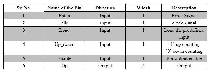
1 . This 4-bit Up Down counter has five input signals and one output signal. Rst_a is asynchronous reset signal. clk is clock signal. Load is used to load counter with predefined input value. Up_down is for counting up or counting down operation. Enable is to enable output signal. Op is four bits wide output signal that will give counted value.
Verilog Code for 4-bit up/down counter is:
module upordown_counter(
    Clk,
    reset,
    UpOrDown,
    Count
    );

    input Clk,reset,UpOrDown;
    output [3 : 0] Count;
    reg [3 : 0] Count = 0;
     always @(posedge(Clk) or posedge(reset))
     begin
        if(reset == 1)
            Count <= 0;
        else
            if(UpOrDown == 1)
                if(Count == 15)
                    Count <= 0;
                else
                    Count <= Count + 1;
            else
                if(Count == 0)
                    Count <= 15;
                else
                    Count <= Count - 1;
     end
endmodule
Testbench for counter:
module tb_counter;
reg Clk;
reg reset;
reg UpOrDown;
wire [3:0] Count;
upordown_counter uut (
.Clk(Clk),
.reset(reset),
.UpOrDown(UpOrDown),
.Count(Count)
);
initial Clk = 0;
always #5 Clk = ~Clk;
initial begin
reset = 0;
UpOrDown = 0;
#300;
UpOrDown = 1;
#300;
reset = 1;
UpOrDown = 0;
#100;
reset = 0;
end
endmodule
Waveform from simulation is:
![Name Value 300 ns ns count[3:0] reset UpOrDown](https://d2vlcm61l7u1fs.cloudfront.net/media%2Fda0%2Fda07aa6a-7bc4-4fd1-baa7-c726c4e157a1%2FphpbUqKQU.png)

