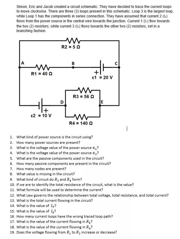
Simon, Eric and Jacob created a circuit schematic. They have decided to trace the current loops to move clockwise. There are three (3) loops present in this schematic. Loop 3 is the largest loop, while Loop 1 has the components in series connection. They have assumed that current 2 (12) flows from the power source in the central wire towards the junction. Current 1 (1) flow towards the two (2) resistors, while current 3 (13) flows towards the other two (2) resistors, set in a branching fashion R2 = 50 A B R1 = 40 2 + £1 = 20 V E w R3 = 56 D E + £2 = 10 v R4 = 140 | 1. What kind of power source is the circuit using? 2. How many power sources are present? 3. What is the voltage value of the power source &,? 4. What is the voltage value of the power source ? 5. What are the passive components used in the circuit? 6. How many passive components are present in the circuit? 7. How many nodes are present? 8. What value is missing in the circuit? 9. What kind of circuit do R, and Rz form? 10. If we are to identify the total resistance of the circuit, what is the value? 11. What formula will be used to determine the current? 12. What Law governs the relationship between total voltage, total resistance, and total current? 13. What is the total current flowing in the circuit? 14. What is the value of 1,? 15. What is the value of 1,? 16. How many current loops have the wrong traced loop path? 17. What is the value of the current flowing in Rg? 18. What is the value of the current flowing in R.? 19. Does the voltage flowing from R, to R, increase or decrease?
Link will be apear in 30 seconds.
Well done! you have successfully gained access to Decrypted Link.
Question:
please only answers. will thumbs-up
Answer:
Solution-
Sum of the answers are as follow which can be given by observation of circuit only
1. DC power source
2. Two
3. E1=20V
4. E2=10V
5. Resistance
6. Four Passive components or four resistances are present.
7. There are four nodes A,C,D,E in the circuit where nodes are the point where more than two wires are connected.
8. Value of current is not given so we can say that it is missing in circuit.
9. Parallel combination circuit is formed by R2 and R3.
Please ask remaining question separately.
Thanks

